The FRAME Architecture (originally called the European ITS Framework Architecture) was developed as a result of recommendations from the High Level Group on transport telematics, which were supported by a resolution of the Council of Ministers. It was created and first published by the EC funded project KAREN in October 2000. The underlying aim of this initiative was to promote the deployment of (mainly road-based) ITS in Europe by producing a framework which would provide a systematic basis for planning ITS implementations, facilitate their integration when multiple systems were to be deployed, and help to ensure inter-operability, including across European borders.
A distinctive feature of the FRAME Architecture is that it is designed to have sub-sets created from it, and is thus unlikely to be used in its entirety. Indeed, on occasions, it contains more than one way of performing a service and the user can select the most appropriate set of functionality to deliver it in that environment. Thus the FRAME Architecture is not so much a model of integrated ITS, as a framework from which specific models of integrated ITS can be created in a systematic and common manner.
The FRAME Architecture now covers the following areas of ITS:
- Electronic Fee Collection
- Emergency Notification and Response – Roadside and In-Vehicle Notification
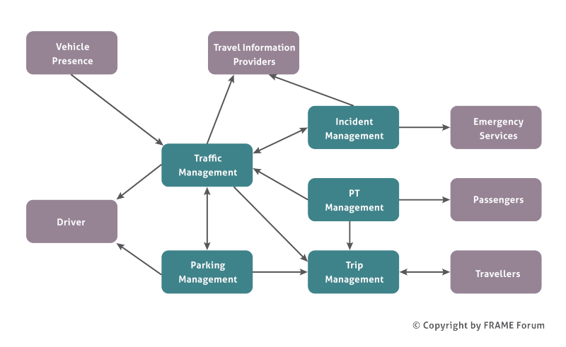
- Traffic Management – Urban, Inter-Urban, Parking, Tunnels and Bridges, Maintenance and Simulation, together with the Management of Incidents, Road Vehicle Based Pollution and the Demand for Road Use
- Public Transport Management – Schedules, Fares, On-Demand Services, Fleet and Driver Management
- In-Vehicle Systems – includes some Cooperative Systems
- Traveller Assistance – Pre-Journey and On-Trip Planning, Travel Information
- Support for Law Enforcement
- Freight and Fleet Management
- Provide Support for Cooperative Systems – specific services not included elsewhere, e.g. bus lane use, freight vehicle parking
- Multi-modal interfaces – links to other modes when required, e.g. travel information, multi-modal crossing management
Because the FRAME Architecture is intended for use within the European Union it conforms to the precepts of subsidiarity, and thus does not mandate any physical or organisational structure on a Member State. It comprises only a set of User Needs which describe what ITS can provide, and a Functional View showing how it can be done. The Methodology, which is supported by computer-based tools, assists the creation of logically consistent sub-sets of the FRAME Architecture Functional View, and the creation of subsequent Physical Views.
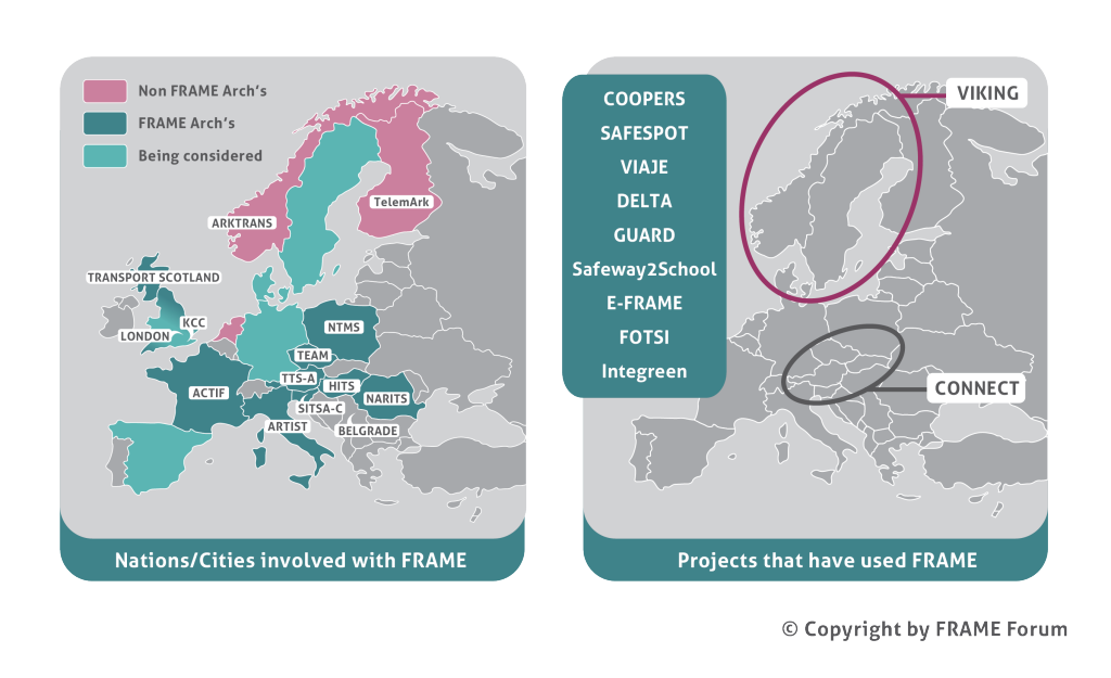
Use of FRAME in Europe
Framework Principle
A principal objective for the FRAME Architecture is to promote the deployment of ITS in Europe by producing a framework which would provide a systematic basis for planning ITS implementations, facilitate their integration when multiple systems were to be deployed, and help to ensure inter-operability, including across European borders.
The FRAME Architecture achieves this objective by providing a model of almost all of ITS from which specific sub-sets of integrated ITS can be created in a systematic and common manner. It covers most ITS applications and services that are currently being used, or being considered for implementation, in Europe, and it does not impose any technical or organisational assumptions on the way things are done.
It therefore provides ITS engineers with a common approach, or “language”, for use throughout the EU.
Because the FRAME Architecture is intended for use within the European Union it conforms to the precepts of subsidiarity, and thus does not mandate any physical view or organisational structure on a Member State. It therefore consists of only a set of User Needs for ITS, and a Functional View that satisfies them; the remainder of the views are created when required. Thus the FRAME Architecture is “neutral” and makes no assumptions about the way things are done.
Use of the FRAME Architecture
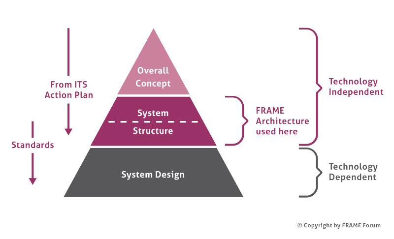
The FRAME Architecture is intended to be used within a top down approach to the planning and deployment of integrated ITS. The overall concept may, or may not, be represented in a formal (reference) model. Since the creation of a reference model requires a number of decisions or choices to have been taken by those implementing and/or regulating ITS, the FRAME Architecture does not provide one.
The overall concept and the system structure should be described in a technology independent way so that, as technology evolves, all the higher level requirements remain unchanged. The information contained within the system structure enables the ITS industry to produce the equipment and systems that will provide the services wanted by the stakeholders, each with their own distinctive features, but conforming to the purposes expressed in the overall concept and system structure. Thus integrated and/or inter-operable ITS services can be provided across the EU.
The system structure contains a number of views. The functionality needed to implement ITS Services is provided by the Functional View; which does not impose any specific technical solutions on its users.
Each specific implementation requires choices to be made by the stakeholders, in particular which components will be used for the ITS implementation and the links between them (the Physical View).
Further analysis, also based on specific choices or decisions, can then provide:
- Communications Viewpoint – the requirements for communications between the components
- Organisational Viewpoint – who owns, manages and operates each components and other organisational issues
- Information Viewpoint – information that is used, its atributes and relationships
The content of the Physical Viewpoint and the Communications Viewpoint can be included in Calls for Tender to enable the components and communications to be procured and deployed. The Organisational Viewpoint is used to enable the correct management structure, plus rules and regulations, to be put in place so that the services can be correctly provided.
The FRAME Model
The FRAME model used for the Functional View is based on hierarchical Data Flow Diagrams. At the highest level is the Context Diagram (see figure below) which shows all the functionality supported by the FRAME Architecture inside a box labelled “System” surrounded by a set of “Terminators”, which are outside the boundary of the system. Each Terminator represents some thing, or person, to which the system will send data and/or from which it will receive data. As there is a large amount of functionality in the FRAME Architecture (2-3000 elements in total), its size is managed using hierarchies of functions and terminators.
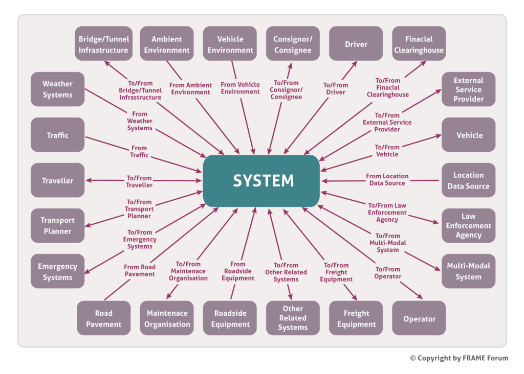
The FRAME System in the figure above is divided into 9 Areas (see below). Each Area then has a number of hierarchical levels of functions as required, with each High-Level Function being decomposed into a number of lower-level Functions until the final Low-Level Functions are reached. Initially it was thought that the High-Level Functions would be used during the sub-set creation process, but it was quickly found that, whilst many of the corresponding Low-Level Functions were required in a given situation, not all them were. That, and the difficulty of following data flows through the hierarchy of functions, has resulted in the High-Level Functions being used solely for convenience when creating or looking at the entire FRAME Architecture. Thus the FRAME Architecture Functional View is now defined with its Low-Level Functions, and the creation of sub-sets is performed using only them.
The name “Terminator” derives from the fact that the data for, and produced by, the System starts/stops there. The FRAME Architecture sub-divides some of its Terminators into a number of Actors. Not only does this make the total architecture more manageable, especially the construction of the diagrams, but it is also useful for situations when some data goes to/from all Actors in the Terminator, e.g. all Drivers, and on other occasions data goes to/from a specific Actor, e.g. Public Transport Driver.
The 9 Areas of the FRAME Architecture
The FRAME Architecture models road based ITS applications and services, and is divided into the following nine broad Areas:
- Provide Electronic Payment Facilities
- Provide Safety and Emergency Facilities – includes both in-vehicle and roadside “eCall” plus the management of the Emergency Services responses
- Manage Traffic – includes urban and inter-urban traffic management, plus parking, incident and demand management
- Manage Public Transport Operations – includes both regular and on-demand services, plus fare cards and vehicle sharing
- Provide Advanced Driving Assistance Systems – includes support for in-vehicle services some of which are part of cooperative systems
- Provide Traveller Journey Assistance – includes both pre- and on-trip planning, plus traveller information
- Provide Support for Law Enforcement
- Manage Freight and Fleet Operations
- Provide Support for Cooperative Systems – includes support for cooperative systems not included elsewhere
Links to other modes of transport are made through the Terminator “Multi-Modal System”, which is used to provide travellers with multi-modal travel information, to manage multi-modal crossings and incidents that take place on other modes.