
Warning!! This Version is not supported anymore!!
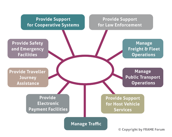
The FRAME Architecture now contains the Cooperative Systems services and applications developed by the COOPERS, CVIS and SAFESPOT FP6 Integrated Projects. This extension now brings the total number of principal Functional Areas supported by the FRAME Architecture to nine, as shown below. A document containing a brief summary of the contents of each Functional Area can be found in download.
The presentation of the User Needs in the Browsing and Selection Tools can be difficult to read en masse, and a so a fully formatted set can be found in download.
Overview
The following is an overview of how the Selection Tool is intended to be used.
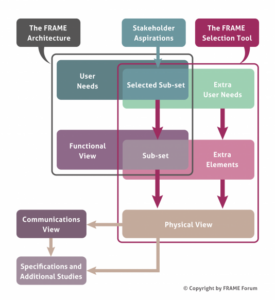
When creating a bespoke ITS Architecture from the FRAME Architecture the architecture team needs to select a sub-set of the FRAME Architecture and, possibly, add some extra functionality that us not currently present. This process is supported by the FRAME Selection Tool which contains a database with all the elements of the FRAME Architecture, and to which more can be added. This is illustrated in the following figure.
Download Area
The FRAME Selection Tool
FRAME Database
User Manual
Reference Manual
System Requirements
The Selection Tool should run on any PC with Windows XP, Windows Vista, Windows 7, Windows 8 or Windows 10.
The Selection Tool won’t work with Office 2016, and in that case the Access 2010 Engine should be downloaded.
Use of the FRAME Selection Tool
The Tool does not perform any selections automatically, but it does support the architecture team in its use of the methodology in the following ways.
- The team selects those User Needs that reflect the Stakeholder Aspirations.
- The tool will then guide the architecture team to those parts of the Functional View that help to satisfy those User Needs.
- The FRAME Architecture does not claim to satisfy every possible ITS User Need, and in some circumstances it may be necessary to add extra User Needs and Functional View elements to the Selection Tool data base.
- Since the mapping from User Needs to Functions is not an exact science, the tool will probably report some logical inconsistencies after the first pass (e.g. a data flow with only the function at one end selected). The team can then select further elements, or deselect some of those already selected, until there are no logical consistency errors, and they are satisfied that their selection fully represents the Functional View needed to satisfy the Stakeholder Aspirations.
- Once a Functional View is considered acceptable, it can be used as the basis for one or more Physical Views. The architecture team does this by allocating functions and data stores to individual sub-systems, and to modules within them if required. Modules are used to partition the functionality in sub-systems so that, for example, the functionality for traffic management can be separated from that for parking management.
- Once a Physical View has been completed one of the reports available from the Selection Tool can be used to provide the starting point for an analysis of the Physical Data Flows. This leads to the creation of the Communications View, which shows the characteristics of the links required between each of the sub-systems and modules, plus those with the Terminators.
- An Organisational View can also be created from a Functional View.
- The Tool permits more than one Physical and/or Organisational View to be created from a Functional View so that the advantages and disadvantages of different component configurations, physical locations and deployment scenarios can be explored.
Thus, although the Selection Tool does not have any intelligence to make decisions on behalf of the architecture team, it does perform much of the detailed work of recording all the decisions taken by them. Experience has shown that it is not normally necessary to produce a Data Flow Diagram of the Function View since all the information required to produce a Physical View is held within the data base.