The FRAME Architecture (originally called the European ITS Framework Architecture) was developed as a result of recommendations from the High Level Group on transport telematics, which were supported by a resolution of the Council of Ministers. It was created and first published by the EC funded project KAREN in October 2000. The underlying aim of this initiative was to promote the deployment of (mainly road-based) ITS in Europe by producing a framework which would provide a systematic basis for planning ITS implementations, facilitate their integration when multiple systems were to be deployed, and help to ensure inter-operability, including across European borders.
A distinctive feature of the FRAME Architecture is that it is designed to have sub-sets created from it, and is thus unlikely to be used in its entirety. Indeed, on occasions, it contains more than one way of performing a service and the user can select the most appropriate set of functionality to deliver it in that environment. Thus the FRAME Architecture is not so much a model of integrated ITS, as a framework from which specific models of integrated ITS can be created in a systematic and common manner.
The FRAME Architecture now covers the following areas of ITS:
- Electronic Fee Collection
- Emergency Notification and Response – Roadside and In-Vehicle Notification
- Traffic Management – Urban, Inter-Urban, Parking, Tunnels and Bridges, Maintenance and Simulation, together with the Management of Incidents, Road Vehicle Based Pollution and the Demand for Road Use
- Public Transport Management – Schedules, Fares, On-Demand Services, Fleet and Driver Management
- In-Vehicle Systems – includes some Cooperative Systems
- Traveller Assistance – Pre-Journey and On-Trip Planning, Travel Information
- Support for Law Enforcement
- Freight and Fleet Management
- Provide Support for Cooperative Systems – specific services not included elsewhere, e.g. bus lane use, freight vehicle parking
- Multi-modal interfaces – links to other modes when required, e.g. travel information, multi-modal crossing management
Because the FRAME Architecture is intended for use within the European Union it conforms to the precepts of subsidiarity, and thus does not mandate any physical or organisational structure on a Member State. It comprises only a set of User Needs which describe what ITS can provide, and a Functional View showing how it can be done. The Methodology, which is supported by computer-based tools, assists the creation of logically consistent sub-sets of the FRAME Architecture Functional View, and the creation of subsequent Physical Views.
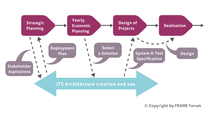
The FRAME Architecture is intended to be used to help the planning and deployment of integrated ITS for a region over a period of time (see diagram below). An ITS Architecture is created for that region to show what is required. Then, in each financial period, a set of applications or services can be chosen and the System Requirements Specification and the Test Specification parts of a Call for Tender can be written using the descriptions obtained from the relevant parts of the ITS Architecture.
A second way of considering the planning process is shown in the waterfall lifecycle below, which shows the tasks to be performed and who performs them. This shows that a typical ITS deployment can be a two stage process. In the first stage a local authority or road operator produces a Call for Tender. In the second stage the company that wins the contract develops and deploys the equipment. An ITS Architecture is created during the first stage and is used to provide many of the details of the Call for Tender.
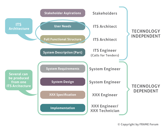
Note – an ITS Architect is an ITS Engineer with a knowledge of ITS Architecture
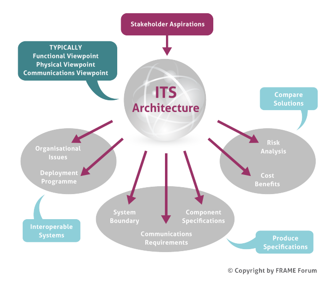
A third way of considering the planning process is shown in the diagram below.
The process begins with the various stakeholder stating what they want from the ITS deployment in a set of Stakeholder Aspirations.
Once an ITS Architecture has been created various issues can be studied and products created as follows:
- System Boundary – Shows what is provided by the system and what is not, and the relationship between the System and the parts of its environment with which it interacts
- Component Specifications and Communications Requirements – for Calls for Tender
- Deployment programme – the plan for he deployment of equipment and communication. This includes what to do with existing systems and equipment
- Organisational View – who owns and/or manages and/or operates each part of the integrated system
- Cost/Benefits Study – the costs and the expected benefits of the ITS deployment
- Risk Analysis – deployment hazards, their risks and possible mitigations
A fourth way of considering the planning process is shown in the diagram below.
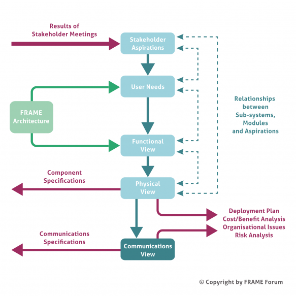
Once an ITS Architecture has been created from the FRAME Architecture the requirements of the communications links (physical data flows) can be compared with existing communications standards and technologies. If these already exist then they should be used, but if not then it may be necessary to initiate their development.
If necessary the ITS Architecture, and its communications requirements, can be analysed as described in the “third way” above, and changes made if found to be necessary.
The ITS Architecture, and its communications requirements, form the basis on which the Procurement Process takes place, which leads to the ITS implementation.
